Things about Wedge Barriers
Wiki Article
7 Easy Facts About Wedge Barriers Described
Some Known Factual Statements About Wedge Barriers
The staying pressure applied to the cam web cam deploy the wedge plate 16 may might provided offered an electromechanical actuator 84 or other various other. The springtime assembly 54 and the actuator 84(e. Wedge Barriers. g., electromechanical actuator)may operate together to equate the cam and lift the wedge plate 16.
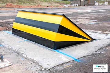
As stated over, the springtime setting up 54 exerts a continuous pressure on the web cam, while the electromechanical actuator might be controlled to put in a variable force on the camera, thereby enabling the lifting and reducing( i. e., releasing and withdrawing )of the wedge plate 16. In particular embodiments, the consistent force applied by the springtime setting up 54 may be adjustable. g., electromechanical actuator) is disabled. As will be valued, the springtime setting up 54 may be covered and shielded from debris or various other elements by a cover plate(e. g., cover plate 68 displayed in FIG. 4) that might be significantly flush with the raised surface area 38 of the structure 14. As stated over, in the released position, the wedge plate 16 serves to block gain access to or travel beyond the obstacle 10. For instance, the barrier 10(e. g., the wedge plate 16 )may block pedestrians or vehicles from accessing a residential or commercial property or pathway. As talked about above, the obstacle 10 is affixed to the support 30 protected within the foundation 14,

front braces 71. As an outcome, the link assemblies 72 may pivot and revolve to allow the collapse and expansion of the link assemblies 72 throughout retraction and implementation of the bather 10. The linkage assemblies 72 reason activity of the wedge plate 16 to be limited. For instance, if a lorry is taking a trip towards the deployed wedge plate 16(e. As an example, in one scenario, the safety and security legs 86 might be prolonged duringupkeep of the barrier 10. When the security legs 86 are deployed, the security legs 86 support the weight of the wedge plate 16 versus the surface 12. Because of this, the lifting device 50 may be shut down, serviced, removed, changed, etc. FIG. 5 is partial perspective sight of a personification of the surface-mounted wedge-style barrier 10, highlighting the camera 80 and the camera surfaces 82 of the click this lifting mechanism 50. Particularly, two camera surfaces 82, which are described as lower webcam surfaces 83, are placed below the camera 80. The reduced cam surfaces 83 might be taken care of to the surface 12 (e. As an example, the lower webcam surface areas 83 and the placing plate 85 might create a single piece that is secured to the anchor 30 by bolts or other mechanical fasteners. In addition, two web cam surfaces 82, which are referred to as top camera surface areas 87, are placed over the cam 80 and coupled to (e. In other personifications, stepping in layers or plates might be positioned between the surface area 12 and the lower cam surface areas 83 and/or the wedge plate 16 and the upper webcam surface areas 87 As mentioned above, the cam 80 translates along the cam surface areas 82 when the wedge plate 16 is home raised from the withdrawed position to the released placement. In addition, as discussed over, the springtime assembly 54 (see FIG. 3 )may give a pressure acting on the camera 80 in the direction 102 through springtime pole 58, which may reduce the force the electromechanical actuator 84 is called for to relate to the camera 80 in order to activate and lift the wedge plate 16. 1 )to the deployed placement(see FIG. 4). As revealed, the web cam 80 includes track wheels 104(e. g., rollers), which call and equate along the web cam surfaces 82 during procedure.
Report this wiki page